‘Secondary’ Preparation Chamber
Typical pressure |
1e-10mBar |
Manipulator axes |
X,Y,Z,Polar |
Heating |
Direct current (>1200° C), filament (700° C), e-beam (1000° C) |
Lowest sample temperature (LN2) |
110K |
LEED? |
Yes |
Crystal growth monitor? |
Yes (on manipulator) |
Sputtering? |
Yes |
Gas dosing? |
Yes |
Cleaving? |
No |
User supplied sources? |
Yes |
Wobblestick
The wobblestick currently installed in Prep Sec is a UHV Design model with their slightly unusual ‘Flag Blade’ end effector. The animation below illustrates how it works:
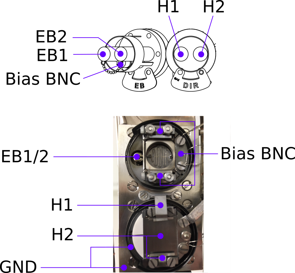
Sample receivers
The PrepSec manipulator has two sample receivers. The upper can perform electron-beam (EB) heating, the lower can perform both direct-current (DC) heating (i.e. pass a current through the sample) and resistive filament heating (RH) (i.e. heat a filament hidden beneath the sample receiver).
Moving the manipulator
There are two options for controlling the manipulator; review the information below and decide which one you prefer. The two different styles of control panel do not share information about saved positions.
Warning
Moving to and from the LEED position has a high risk of collision if the LEED unit is not retracted!
Option 1: ‘New’
Double-click on ‘NewPSManip.sh’ on the desktop. This panel has a similar design to the Carving manipulator control panel.
When using this panel, you can also bring up a second ‘Automap’ panel similar to the one used with the Carving, that will keep a record of where the manipulator has been and allow you to program simple x-y raster scans. This can be useful when searching for a LEED pattern, or to raster the sample in front of the sputter beam.
Note
This panel is not (yet) clever enough to deal with the sample being polar-rotated during LEED or sputtering. So you will be raster scanning in the X-Z plane, not in the plane of the sample surface
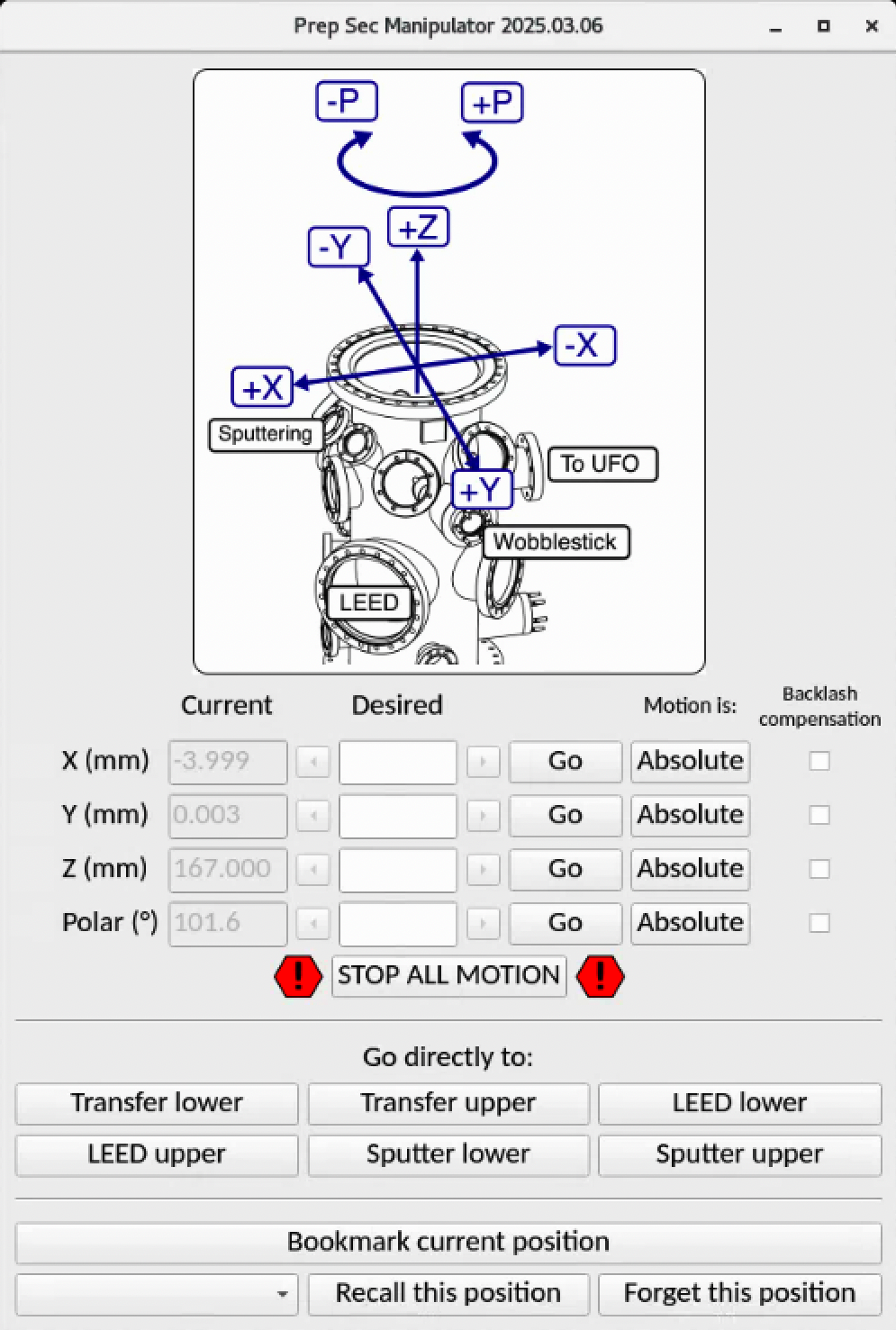
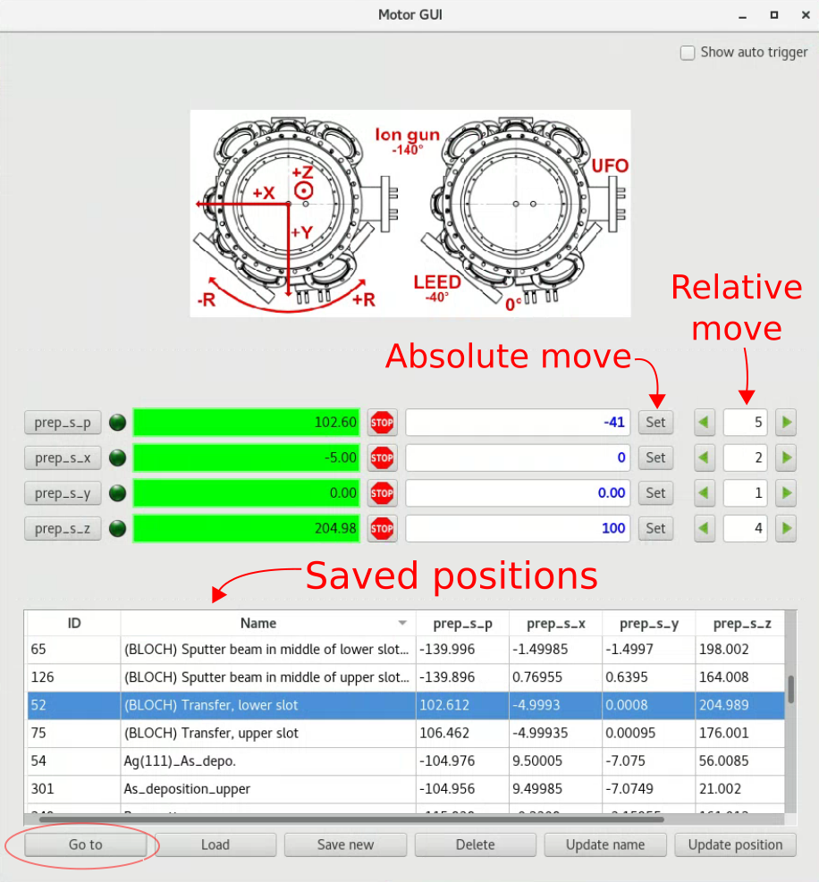
Option 2: ‘Classic’
Run the ‘BlochControlsGUI’ shortcut on the desktop, then choose ‘Manipulator PS’ under ‘ARPES endstation’
When it first opens it is missing the drawing of the axes and the list of saved positions. These are enabled by pulling on almost invisible horizontal lines:
This gives you absolute or relative motion control of all axes. There is also a list of saved coordinates. Positions prefixed by (BLOCH) have been set and checked by us, everything else is to be trusted at your own risk. To go to a position, select it and push the ‘Go to’ button.
Sputtering
(See also the dedicated Sputtering page)
Sputter current can be measured in both sample slots, with the important caveat that in both cases, what is being measured is the total sputter current impinging on the entire sample plate. It is not necessarily the flux onto your sample.
In the lower (DH/RH) slot, connect a suitable ammeter (e.g. Keithley 6485) between the H2 terminal and the grounded chamber chassis. Manually ground the H1 terminal.
In the upper slot (EB), connect the meter between the bias BNC and the grounded chamber chassis. This measurement is only possible when there is no emission current from the ebeam filament.
We have a dedicated test sample for locating the size and position of the sputter beam at normal incidence, so the saved manipulator positions should correctly position your sample in front of the beam.
Remember to ground the BIAS or H2 terminals when you remove the ammeter, otherwise the sample can charge while sputtering.
It is possible to heat while sputtering, but you need to turn off or bypass the ion gauge to avoid tripping an interlock on the HEAT3 unit.
Heating
There is a compressed air line close to the PrepSec chamber that can be used to air-cool the manipulator. This useful for improving the chamber pressure while operating the sample heaters.
Direct current
The wiring on the manipulator is rated for 10A continuous current. Slightly higher values are OK for durations of a few minutes. Ask first if you need to go much higher.
Resistive
There is a tungsten filament hidden underneath the sample receiver. The connections to this filament are also located at the top of the manipulator and labelled ‘H1’ and ‘H2’, but have their own feedthrough labelled ‘RES’.
To prolong the life of the filament, we ask that you ramp the filament over a period of at least a minute, and stay below a current of 8A. If you need higher temperatures, it is better for the equipment and for the chamber pressure if you use e-beam heating instead.
It is possible to use the Prevac HEAT3 controller in the rack to run this heater, but if you wish it is also possible to bring a simple DC power supply close to the chamber and use that.
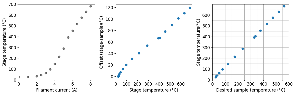
There is a thermocouple mounted to the sample stage, but due to the loose clamping of sample plates in the stage your sample will always be cooler than the thermocouple reading.
The calibration chart below was made using a flat-plate sample with a thermocouple spot-welded to the surface (March 2025). There was no air cooling running, and between each increment in current 5 minutes settling time was allowed. Running air cooling or waiting a different amount of time will change the mapping between filament current and stage temperature, but the mapping between stage temperature and sample temperature should always be valid.
E-beam heating
The upper receiver is for electron-beam heating. Here the sample is grounded and the filament and the shield surrounding it are raised to high voltage. Temperatures of up to 1000° C are achievable. To provide the high voltage, it is necessary to use the Prevac HEAT3 controller in the rack.
The bias BNC must have a grounding plug installed when ebeam heating, otherwise the sample stage is electrically floating and the emitted electrons find some other grounded component to go to.
Like the resistive heating stage, a thermocouple is mounted on the sample receiver. Since it is the sample plate itself being heated and not the receiver, here the thermocouple always under-reads the sample temperature, sometimes by several hundred degrees. You must use a pyrometer to monitor your sample temperature, and never use the automatic PID control option in the HEAT3 controller.
With no high-voltage applied, the heater can be operated as a simple resistive heater. Since the filament is thin and fragile, you must treat it very gently - slow ramps and never more than 3.3A.
With e-beam heating, aim to fix the filament current at the lowest value you can that still reaches the desired temperature. Temperature control is then by setting the high voltage, 0-1kV.
Quartz crystal thickness monitor
On the reverse side of the bottom of the manipulator there is a water-cooled quartz crystal microbalance (without shutter). It is 43.5mm below the center of the resistive heating stage, and 79.5mm below the center of the ebeam heating stage.
The operational procedure is not yet documented, consult with beamline staff if you need this.
LN2 cooling
With a pressurized dewar it is possible to send LN2 directly into the cooling line of the manipulator. In practice this is difficult since there is not a vacuum insulated transfer line to connect the two.
An alternative, easier approach is to use a heat-exchanger coil. Here N2 gas is sent through the manipulator, but before entering it passes through a copper coil immersed in a small polystyrene dewar of LN2. The heat transfer is very effective and can partially liquify the N2.
Base temperature with this technique is 89K on the receiver thermocouple, 112K on the sample plate (due to a lack of clamping) with a cooldown time of 20 minutes. Only the lower receiver is cooled
The operational procedure is not yet documented, consult with beamline staff if you need this.