How to run the beamline
Control GUIs
How to launch control GUIs
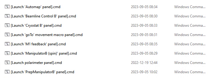
For the control panels on the Windows spectrometer control computers, there is a folder on the desktop called ‘ControlGUIs’. Within this you will find all of the control GUIs discussed below. All of them have a corresponding ‘Launch’ shortcut that you can double click on.
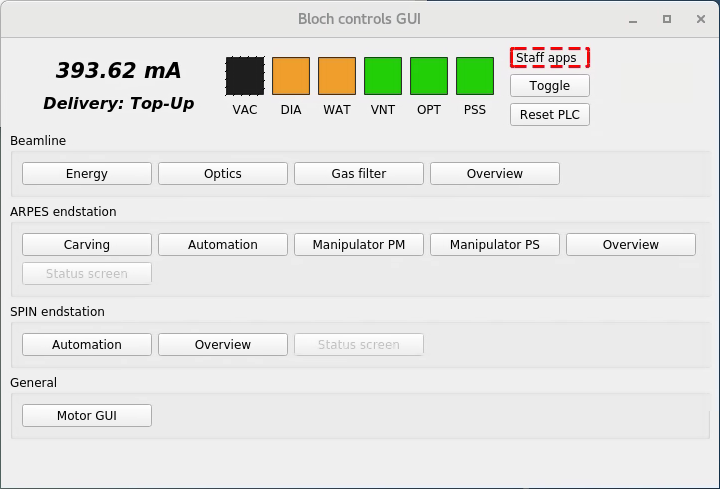
For the control panels on the ‘beamline’ control computer (Linux) there is a ‘Bloch controls GUI’ shortcut on the desktop that brings up a launcher for all the sub-panels.
There is some redundancy between what you can do with the controls on the two different computers. As a general rule, the panels on the Linux computer are more full featured while those on the Windows computer are simplified and cover only what is needed in a typical experiment.
Beamline control panel (Windows computer)
Note
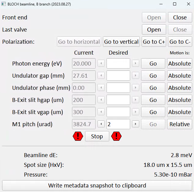
The design ‘philosophy’ of this and all similar panels is to disable anything that is not possible from your current state. In this way it also informs you about the current state. For example, in the screenshot above the ‘Close’ button for the front end is greyed out. This is because it’s already closed, so the only possible action would be to open it.
Front end and last valves
‘Front end’ here refers to the set of valves and shutters immediately following the undulator. It must be open to receive beam on the sample. It will automatically close if there is an interlock condition or a beam dump.
‘Last valve’ is the final pneumatic valve isolating the endstation from the beamline. Remember to close it as a precaution whenever you are transferring samples.
Setting photon energy / polarization
When you request a photon energy, you are dealing with a higher-order system that will automatically configure the monochromator and undulator correctly. This system can recognize which polarization mode you are in by examining the undulator phase:
Phase = 0 mm is interpreted as horizontal polarization
Phase = 42 mm is interpreted as vertical polarization
Any intermediate phase, positive or negative is interpreted as circular polarization.
The polarization buttons on the control panel change the undulator phase and then ‘wobble’ the photon energy up and down by 0.1eV in order to trigger the higher-order process to configure the undulator correctly for the desired photon energy.
Note that while this panel exposes the undulator gap and phase, under normal circumstances you will not need to adjust these.
Exit slits
The exit slit horizontal gap determines energy resolution, vertical spot size and flux.
The exit slit vertical gap determines horizontal spot size and flux.
When measuring ARPES typical values are (100μm x 100μm), but it is not unusal to need to close down much further in order to avoid damaging the detector. Aligning the sample in transmission mode requires settings more like (15μm x 15μm) to avoid damage. If you don’t care about spot size, flux will continue to increase for vertical gap values up to around 700μm, and the same for horizontal gap if you don’t care about energy resolution.
The estimated beamline resolution and spot size on the sample is estimated at the bottom of the panel based on your current settings.
M1 pitch
One of several functions of the first mirror (‘M1’) is to deflect the beam horizontally. If the mirror pitch is not optimized, the beam does not ‘thread the needle’ through the downstream optics and photons are needlessly lost. M1 pitch is set automatically by a supervisor script (see below), but if this is not behaving for some reason then you will need to manage the M1 pitch by hand. Very low (<20eV) photon energies are high heatload conditions where you can expect time drift of the optimal M1 pitch value. The consequence of imperfect M1 pitch is a substantial loss of flux, and it can be optimized by manually stepping it (typically 2urad steps) while watching the countrate - the response curve is gaussian and the optimal position should be obvious. Seek advice from beamline staff before attempting very low energy measurements.
Write metadata snapshot to clipboard
This is an optional convenience function to work around the dearth of beamline metadata saved by SES. Besides analyzer and scan settings, currently only manipulator position and photon energy are saved in measurement metadata. Pressing this button will paste a metadata string to the clipboard, which you can then paste into the comments field in the sequence editor. SES does not allow ‘ctrl+v’ pasting, you need to right click and select paste.
M1 pitch corrector (Windows computer)
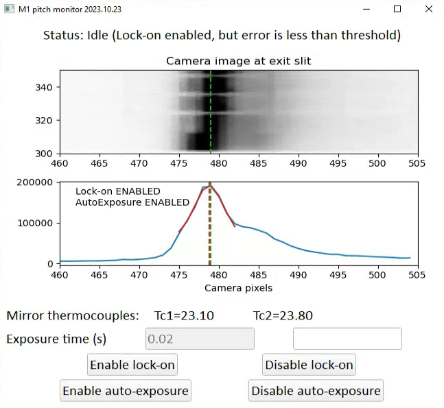
This panel is responsible for running a feedback loop to keep M1 pitch at the optimal value. It does this by examining a camera view of the fluorescent coating on the exit slit horizontal gap blades, which gives information about the horizontal beam position. When the window is first opened it defaults to an idle state. You can choose to enable or disable the feedback control (“lock-on”) and the automatic scaling of exposure time to either boost signal or avoid clipping (“auto-exposure”). The recommended state is to enable both.
The mirror thermocouples indicate the temperature measured on the back side of the M1 mirror. As currently configured, if either of these values exceed 40 an interlock will trigger and close the beamline.
Energy panel (Linux computer)
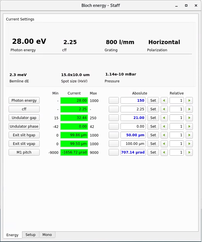
Similar to the ‘Beamline control panel’ on the Windows computer, except now you have some additional options. Among them:
You can change the cff setting of the monochromator for higher intensity or higher resolution (proceed with caution, the energy calibration is only checked for cff=2.25)
In the ‘Setup’ tab you can change monochromator gratings (never do this without first discussing with staff, and note that at present only the 800 l/mm grating is fully commissioned)
Optimizing flux
If you need a higher countrate, your options are as follows, in approximate order of preference:
Optimize the sample focus and/or find a better place on the sample (free)
If the feedback script is not running, fine tune the M1 pitch (free)
Use a larger exit slit vgap, up to 800μm (increases spot size)
Use a larger analyzer slit or higher pass energy (lowers resolution)
Use a larger exit slit hgap (lowers resolution)
Detune the undulator to a slightly higher gap - go in steps of 0.1mm (may worsen higher order contamination)
If you are instead concerned about beam damage and you want a deliberately lower flux, your options are, in order of preference:
Detune the undulator gap
Detune M1 pitch
Note that closing the exit slits is not a good solution for avoiding beam damage - this truncates the beam, which will reduce the total flux on the sample but not the flux density.