How to analyze spin data
Preliminaries
Detailed document deriving polarization equations for the Bloch system
Recommended literature:
Book: (1985) Kessler, Polarized Electrons
Review article: (2009, Meier, Dil and Osterwalder) Measuring spin polarization vectors in angle-resolved photoemission spectroscopy
Review article: (2009, Dil) Spin and angle resolved photoemission on non-magnetic low-dimensional systems
Review article: (2013, Okuda and Kimura) Spin- and Angle-Resolved Photoemission of Strongly Spin–Orbit Coupled Systems
Review article: (2019, Dil) Spin-and angle-resolved photoemission on topological materials
Polarization terminology
An ensemble of electrons is said to be polarized if there exists a direction for which the two possible spin states are not equally populated.
In a fully polarized beam, there exists a direction in which all spins are perfectly aligned.
In a completely unpolarized beam, there is a perfectly equal mixture of all spin alignments.
A partially polarized beam (e.g. `40% Pz+’) should be considered as having some fraction of the electron ensemble perfectly aligned (e.g. 40 out of 100 are pure spin up), and the remainder an equal mixture of spin up and down (e.g. 30 spin up and 30 spin down).
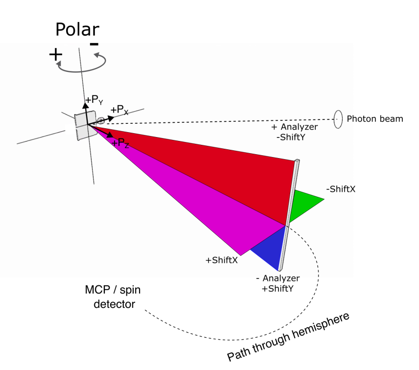
The spin detector at Bloch
Convential wisdom is that Stern-Gerlach style spin filters are not possible with electrons, because unlike atomic beams, electrons are always charged and so experience a strong Lorentz force. Instead, spin polarimeters available today are based on spin-dependent scattering effects. Specifically, spin-orbit scattering (Mott detectors) or exchange scattering (VLEED). The detector at Bloch is a commercial Ferrum VLEED, using an oxidised iron film grown on a tungsten substrate and magnetized in an in-plane direction. The action of a spin rotator before the Ferrum makes it possible to access all three spin directions.
A basic measurement `unit’ consists of two intensity measurements acquired with different target magnetizations, often referred to in terms of the index and polarity of the electromagnet coil set that controls the target magnetization.
If you do this basic measurement with `coil 1’, you have enough information to determine the magnitude of the Pz spin component.
If you do this with `coil 2’, and you already know with certainty what one of (Px,Py) is, you have enough information to get the other one.
If you do this with `coil 2’ for both rotator settings, you have enough information to determine the Px and Py components without making assumptions.
Depending on your experiment, you will typically collecting 4 or 6 intensity measurements to determine spin polarization. Obviously the best is to make no assumptions about your sample and always do 6-EDC sets, but since the measurements are performed sequentially unlike in a Mott detector, this costs you time.
Analysis
This is a simplified summary. For full details, see this document
The raw intensity values for the two coil magnetizations can be combined into an asymmetry:
For the Pz component it suffices to do this with `coil 1’ and any spin rotator setting, and the spin polarization of the incoming electrons is:
Where S is the Sherman function - typically 0.29 for this detector.
For the Px/Py components, we need to combine the asymmetry terms measured with each spin rotator setting:
Using the polarization we can calculate component intensities, i.e. decompose the total spin-integrated measurement into the contributions from each spin direction.
Coordinate systems
So far in the discussion the coordinate system (Sx,Sy,Sz) has been that of the spin detector. But what you ultimately care about is the polarization in the sample coordinate system. In the special case where the sample is at normal emission, all results map directly to the sample (e.g. Sz = out of plane component).
In a real experiment this will not typically be the case. When acquiring from a finite tilt or polar angle, we now have to perform a transformation back into the sample coordinates in order to get the mangitude and directions of the spin polarization correct. For example, if the sample has been rotated to an off-normal polar angle, now an in-plane spin polarization in the sample frame has a finite projection onto the detector Sz axis:
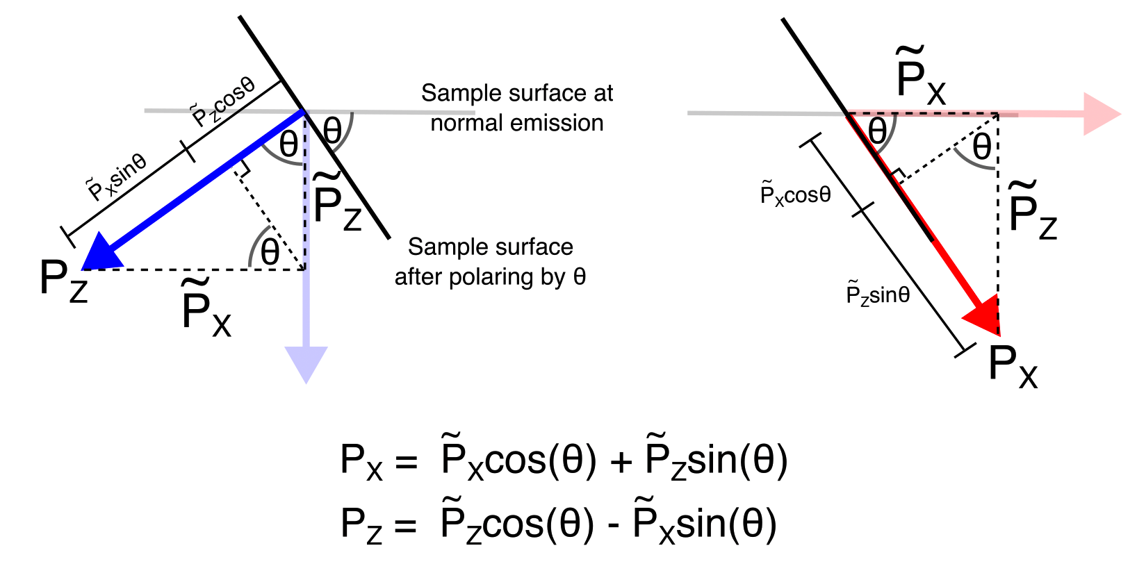
In this figure \(P_{X}\) means the X component of polarization in the sample coordinate system, while \(\widetilde{P_{X}}\) is the X component you measure in the detector coordinate system.
Note that this correction does NOT apply when using the deflectors (since the deflection is electrostatic and does not alter the spin). If the sample is at normal emission, no correction is needed for any point in a deflector map. If you have polar rotated and then performed a deflection map, every point in the map would be corrected in the same way, according to the manipulator offset angle.
Example: WSe2
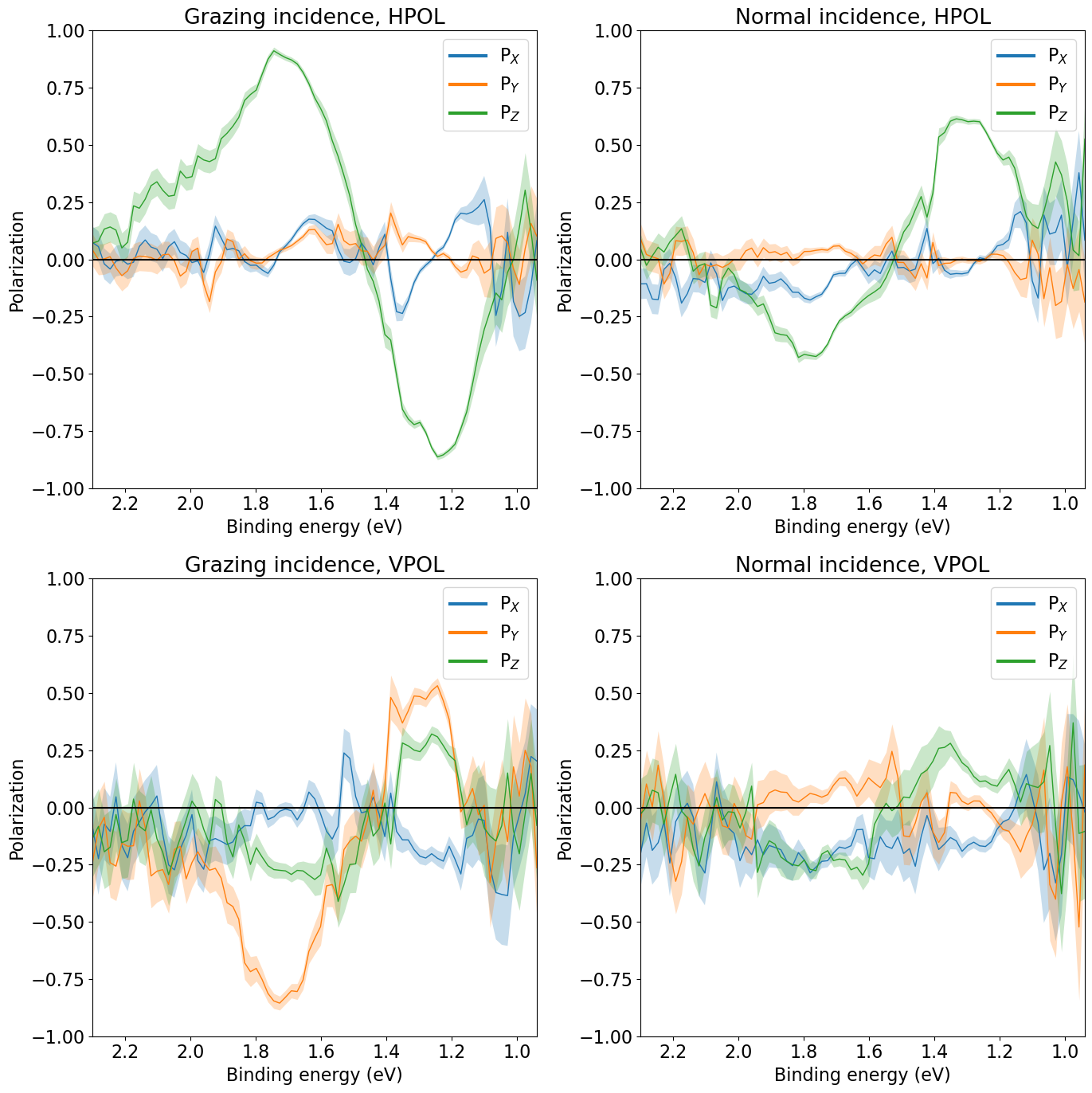
While bulk WSe2 is inversion symmetric, ARPES from the surface exhibits very strong spin polarization at the K points, up to 100% for specific conditions of geometry, photon energy and polarization. Here we show spin-resolved EDCs at hv=27eV for two polarizations and two polar rotations (probing K and K’). This dataset serves as a good example of how difficult it can sometimes be to interpret spin-ARPES spectra in terms of initial state spin polarizations.
Example: Au(111)
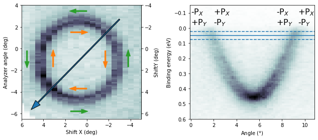
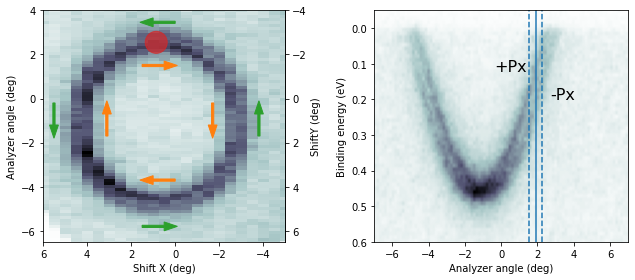
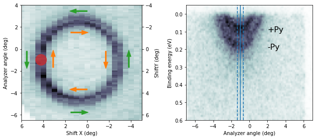
The Rashba-split surface state on Au(111) is a common reference sample for spin-ARPES systems, exhibiting a purely in-plane tangential spin texture.
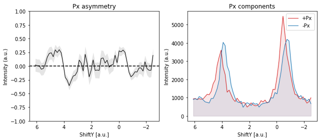
If the sample is at normal emission and we measure the Rashba splitting by tilting the sample (mechanically or with deflector ShiftY), the expected spin polarization in the sample frame is pure Px.
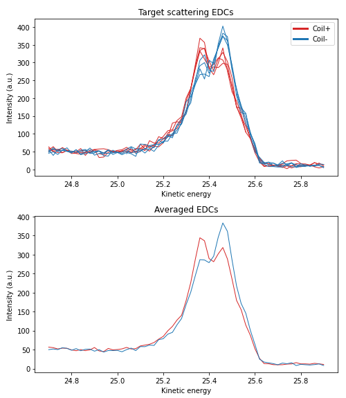
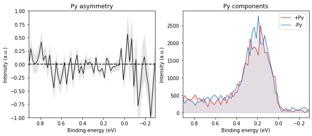
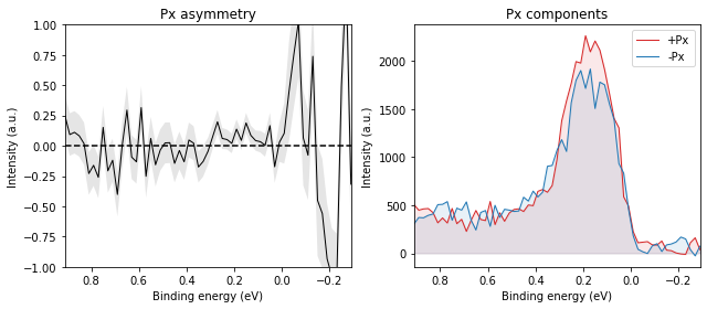
A typical example of a standard EDC measurement set for a single coil polarity is shown below:
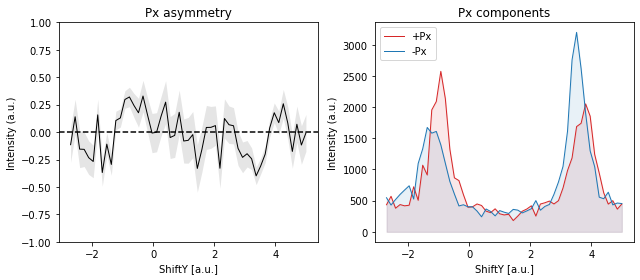
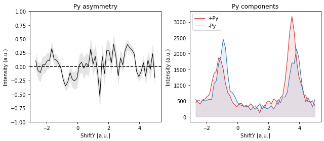
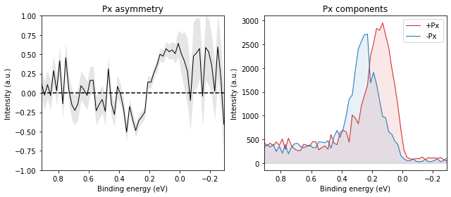
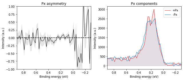
while two polarities combined into asymmetry and thence polarization looks like:
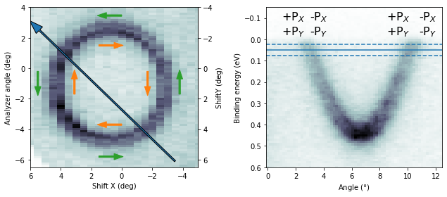
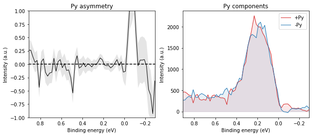
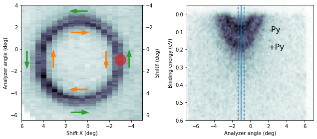
And it should reverse when we measure on the other side of the Brillouin zone:
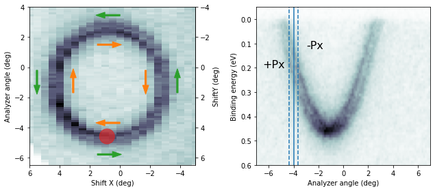
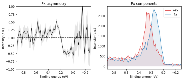
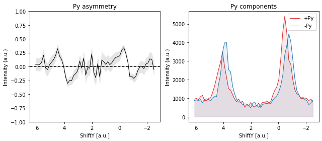
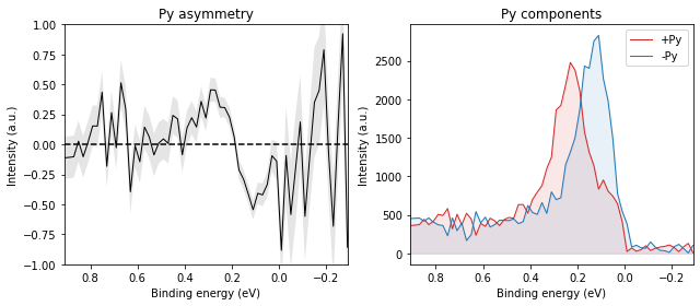
If the sample is at normal emission and we measure the Rashba splitting by polaring (mechanically or with deflector ShiftX), the expected spin polarization in the sample frame is pure Py.
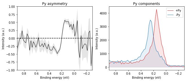
And again, it should reverse when we measure on the other side of the Brillouin zone:
MDC cuts will involve both Px and Py components: