The Bloch beamline
Overview
Ring
The 1.5GeV operates today with 500mA stored current and a 10 minute top-up period.
The 6nm rad horizontal emittance is not comparable to the very low emittance of the 3GeV ring (200pmrad), but is nonetheless competitive with state of the art third generation storage rings elsewhere in the world. The beam size achieved in the center of the Bloch insertion device is 185μm (H) x 13μm (V).
EPU
Bloch is sourced by an in-house built quasi-periodic APPLE II type Elliptically Polarizing Undulator (EPU). It has 28 periods of vertical and horizontal pairs of glued permanent magnets. The period length is 84mm and the minimum magnetic gap is 14mm resulting in a minimum photon energy of 7.45eV for horizontal linear polarization. A quasi-periodic magnet configuration has been used, which shifts higher harmonics away from integer multiples so that they are not passed through the monochromator. As shown below, this concept works well with the exception of the third harmonic in vertical polarization.
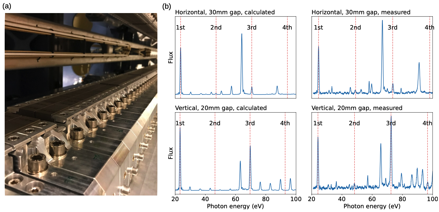
Today we offer horizontal, vertical and circular polarization with no special considerations. Inclined modes are also possible on request. Work is ongoing to further develop circular and inclined modes, with the goal of offering very high purity and well characterized polarization even in regimes where the beamline optics introduce distortions.
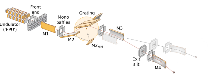
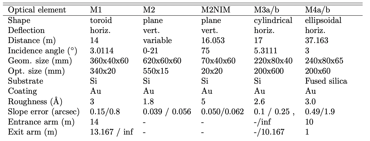
M1
The first optical element of the beamline (M1) is a toroidal mirror, positioned 14m after the source, that collimates the beam vertically and focuses it horizontally on to the exit slit. It takes the bulk of the heat load, and for this reason the pitch angle requires some supervision for high-heatload conditions below 20eV photon energy.
Monochromator
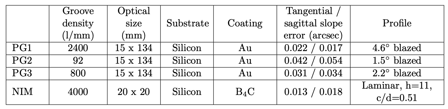
Bloch uses a collimated plane-grating monochromator (cPGM), placed two meters downstream of M1, which introduces a vertical beam offset of 42mm. It can be reconfigured into a normal incidence monochromator (cNIM). The standard configuation is cPGM mode with the 800l/mm grating, but there are two additional cPGM gratings installed to afford flexibility in configuring the appropriate intensity vs. resolution tradeoff. Relative to the 800l/mm configuration, the 2400l/mm offers higher resolution while the 92l/mm grating sacrifices resolution for intensity and is mainly intended for spin-resolved measurements on the second station. The 92l/mm grating can also be used for better preservation of circular polarization. Technical specifications of the gratings are provided below.
The NIM mode was included in the monochromator design to preserve the photon beam polarization produced by the undulator at low photon energies and also to suppress higher order light. It has its own grating and M2 mirror. This mode, as well as the 92l/mm and 2400l/mm cPGM gratings, have been installed and tested, but have not been thoroughly calibrated. Discuss with beamline staff if you wish to use them. Today most users work exclusively on the 800l/mm grating throughout the entire photon energy range.
M3
Positioned 1m after the monochromator, M3a and M3b are cylindrical mirrors that focus the beam vertically on to the exit slit of branch A and branch B, respectively. The swapping of the beam between the branches is accomplished by translating the respective mirror horizontally into the beam.
Exit slits
The exit slits of both branchlines are positioned 10.2m after the M3 mirrors. The size of both the horizontal and vertical exit slit openings can be controlled, as well as their longitudinal position along the beam.
M4
The final optical element on each branchline is an ellipsoidal re-focusing mirror (M4a/b) positioned 10m after the exit slit. It refocuses the diverging beam leaving the exit slit to the sample position, 1m away in the analysis chamber. The refocusing is such that a ratio of 10:1 is achieved, i.e. an exit slit setting of 100μm (hgap) x 100μm (vgap) will result in a beam size of 10μm (H) x 10μm (V) at the sample position.
Energy resolution
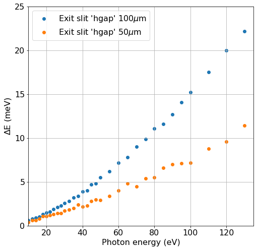
The beamline energy resolution is determined by the photon energy, the grating, the exit slit hgap and the monochromator cff setting. The standard, default mode of operation today is to stay on the 800l/mm grating with cff=2.25. The expected resolution in that case, based on ray-tracing is shown below:
An interactive resolution calculator is also available within pesto, which will provide the ray-tracing resolution estimates for all three cPGM gratings for all photon energy and hgap combinations.
The energy resolution of the beamline has been characterized by measuring photoionization (Rydberg) features in a gas cell containing He (62.8eV) or Ne (21.5eV), and in general slightly outperforms the ray-tracing calculations. The flattening of the energy resolution at small slit width is due to the diffraction limited source size.
Higher resolution can be obtained by either going to a higher cff value (costs intensity and worsens high order contamination) or changing to the 2400l/mm grating (costs intensity). Note also that the monochromator calibration is currently only actively maintained for the default setting (800l/mm, cff 2.25), so you may encounter energy shifts when changing.
Finally, remember that what ultimately matters is the total energy resolution including broadening from the analyzer, and the latter is often what dominates particularly at higher kinetic energies that demand high pass energies. While the analyzer was shown to be capable of 1.9~meV energy resolution in factory acceptance tests, in the real installation grounding issues and electrical noise can dramatically degrade this to more like 5-10~meV.
Flux
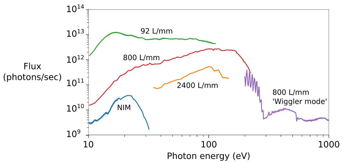
The beamline flux has been characterized for all modes of operation using a silicon diode (IRD XUV100G) placed after the final M4 mirror. The plot below gives an overview of the flux and working range for each mode. Note that here the curves correspond to a fixed cff of 2.25 and a fixed exit slit size of 100μm (hgap) x 100μm (vgap), corresponding to the minimum spot size. If a larger horizontal spot size can be tolerated, the flux can be increased by around a factor of 4 by opening the exit slit vgap to 800μm.
Below 200eV, all curves follow the first harmonic of the undulator. Above this value the undulator gap is closed to a fixed value and its broadband wiggler-mode output is used.
Spot size
The refocusing method at Bloch is based on a single ellipsoidal mirror that directly images and demagnifies the beam at the exit slit to the sample position. A consequence of this is that baffling the beam at the exit slit is reflected as a decreased image size. In the vertical direction this comes naturally when closing the exit slit to improve energy resolution. The inclusion of a horizontal exit slit allows reducing the horizontal spot size by truncating the beam.
On the A station we can achieve a spot size at normal incidence of slightly better than 10μm x 10μm with 100μm exit slits, On the B station where the fine tuning is still in progress, we can achieve 12.5μm x 15.5μm with 100μm exit slits.
Closing the exit slits to openings smaller than 100μm (hgap) x 100μm (vgap) does not reduce the spot size any further, as the limiting factor then becomes the slope errors of M4. Note that since most samples are measured closer to normal emission than normal incidence, the horizontal footprint of the beam on the sample is typically enlarged by 35%.
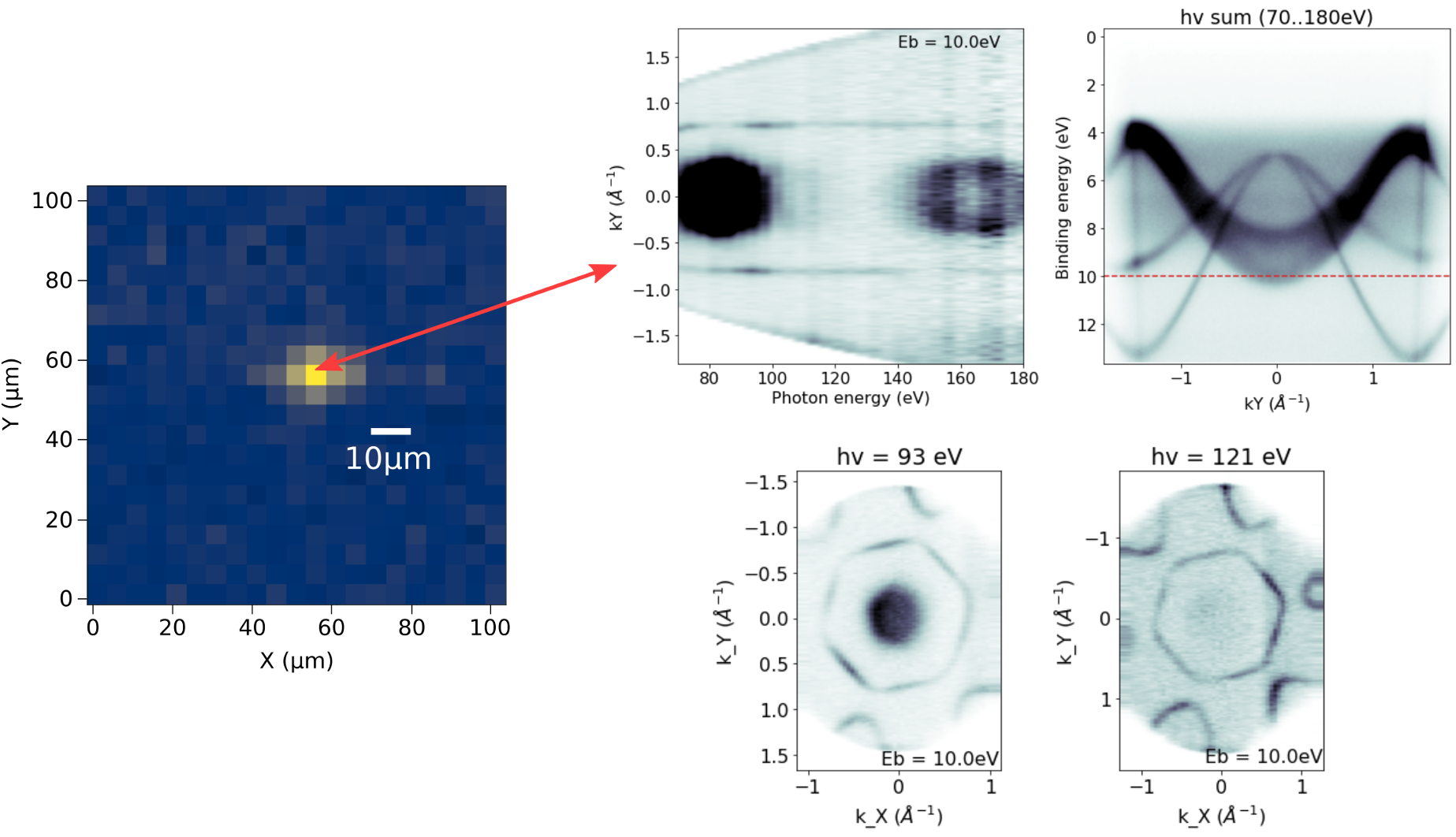
The spot size at the sample position is verified using a test sample containing lithographically patterned Au on a Si substrate. By tuning the spectrometer to a feature unique to Au (e.g. Au 4f core level at higher energies or metallic Fermi edge at low energies) and scanning the sample across the beam, the resulting spectrum reflects the lithographic pattern convolved with the photon spot size.
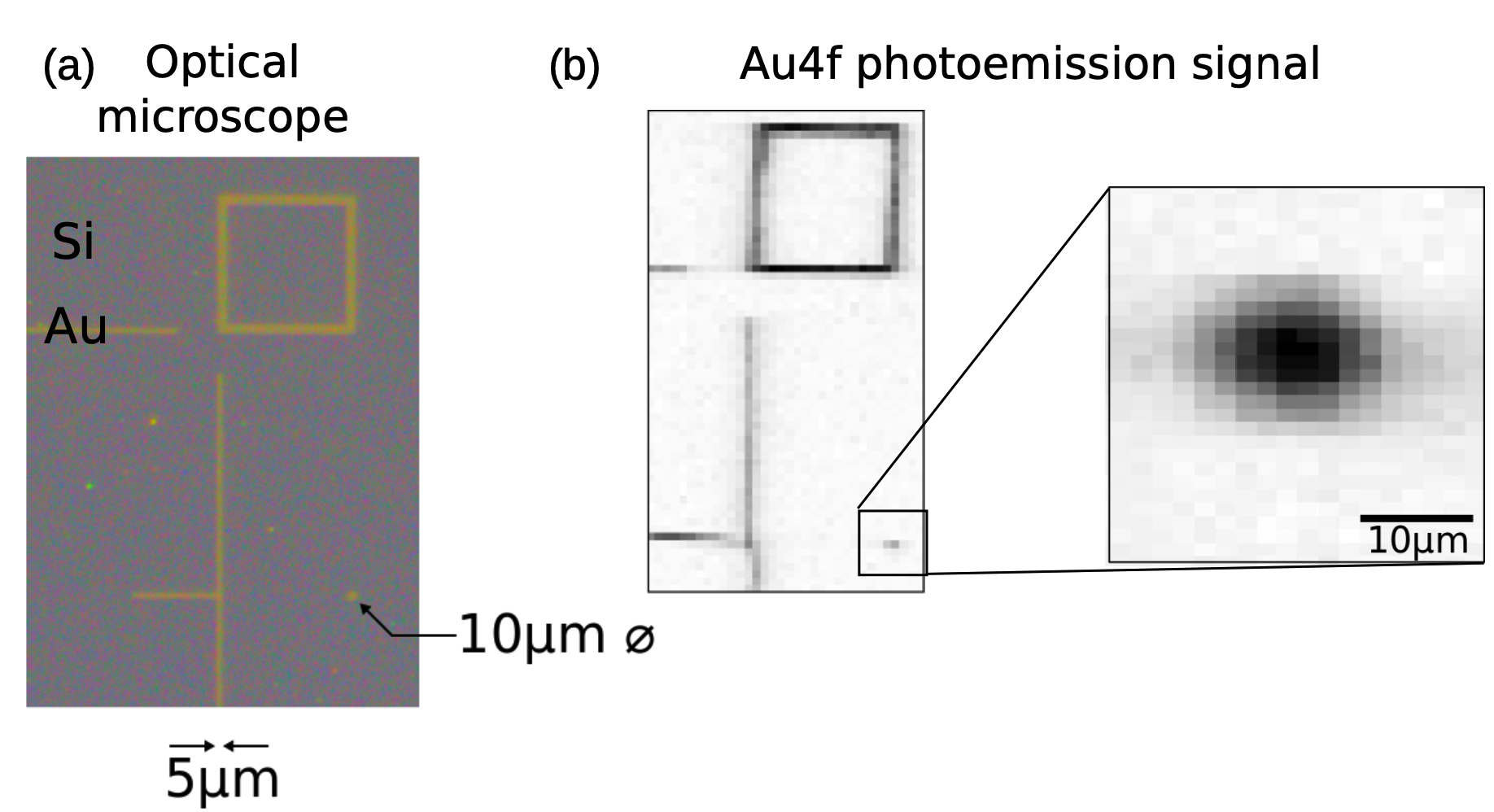
Since the beam on the sample is just a demagnified image of the exit slits, the position should not move when changing photon energy. We have confirmed this with measurements on a small exfoliated flake: