Basler sample cameras
The primary sample camera for the A-endstation measurement chamber is a Basler a2A4096-44g5c (IMX545 sensor, color, 4096px x 3000px) paired with a KX Infinimax lens, with an MX-2 objective and ‘2x power module’. This delivers a fixed magnification of 1.6x at a working distance of 270mm.
As the camera has a native per-pixel resolution of 2.7μm x 2.7μm , this combination translates to a per-pixel resolution of 2.7/1.6 = 1.7μm, with a field-of-view of 4mm x 4mm.
It is mounted on a CF40 window, directly above the analyzer and angled 45 degrees downwards. The working distance is 270mm.
Here is an example image of a small sample. This substrate fluoresces under the beam so we can see the light spot directly:
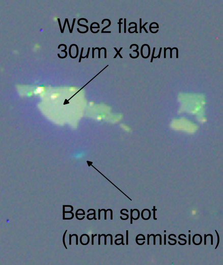
On the B-endstation the camera is a Basler a2A4504-27g5c (IMX541 sensor, color, 4504px x 4504px) paired with a the same KX Infinimax lens.
Starting a video stream
Both cameras have a direct ethernet link to the respective measurement PC. Adjusting settings and viewing the stream is done through the pylon Viewer software, launched from the desktop.
Note
The camera settings are stored on the camera itself. They are not reset if Pylon Viewer closes, but they are reset if the camera is power cycled.
When you first launch pylon Viewer you will see this:
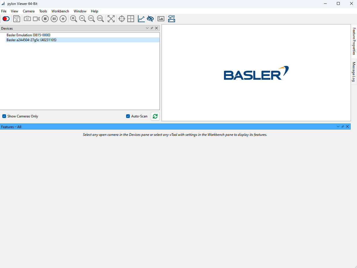
Select the sample camera in the ‘Devices’ pane and press the red toggle switch in the upper left corner to connect to it. This should change the screen to something like this:
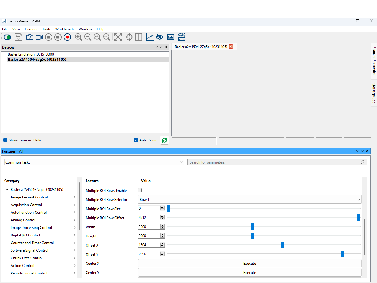
Certain settings are only possible to change when the camera stream is not yet running. In the ‘Image Format Control’ tab you can adjust the Width and Height parameters. We typically reduce this to 2000x2000 pixels to reduce the bandwidth demands. OffsetX and OffsetY can be adjusted at any time, and will adjust which subset of the full resolution image you are collecting.
To start a video stream, press the video camera button (3rd icon to the right of the toggle switch that is now greeen). A video stream has now started in the upper left panel. You can click-drag it out of the pylon Viewer window to position it where you like. The camera image can be panned (click+drag) or zoomed (ctrl+mousewheel) freely.
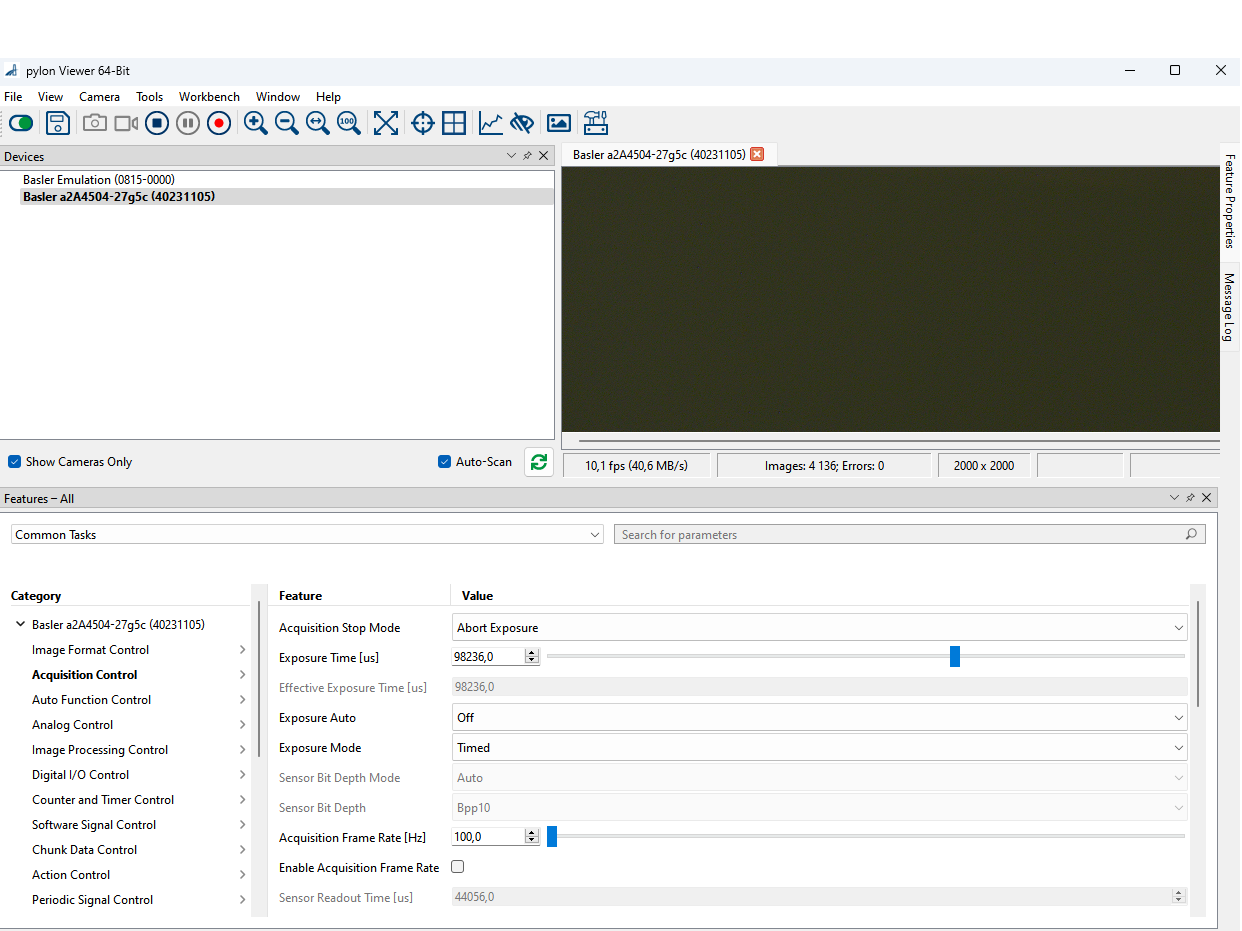
The other setting of interest is the Exposure Time setting in the ‘Acquisition Control’ panel. This can be adjusted while the video stream is running.
Crosshairs
Right clicking on the video stream gives the option to reposition the cross hairs if desired (lock/unlock crosshair). The ‘reference’ value is noted in a txt file in the Control GUIs folder.
Frame errors
Sometimes when the camera has been power cycled or the ethernet port has changed, starting the camera stream will result in nothing but error frames. The typical fix for this is to right click on the camera in the Devices panel and choose Bandwidth Manager. Click on Optimize, and then Start Analysis in the lower left.
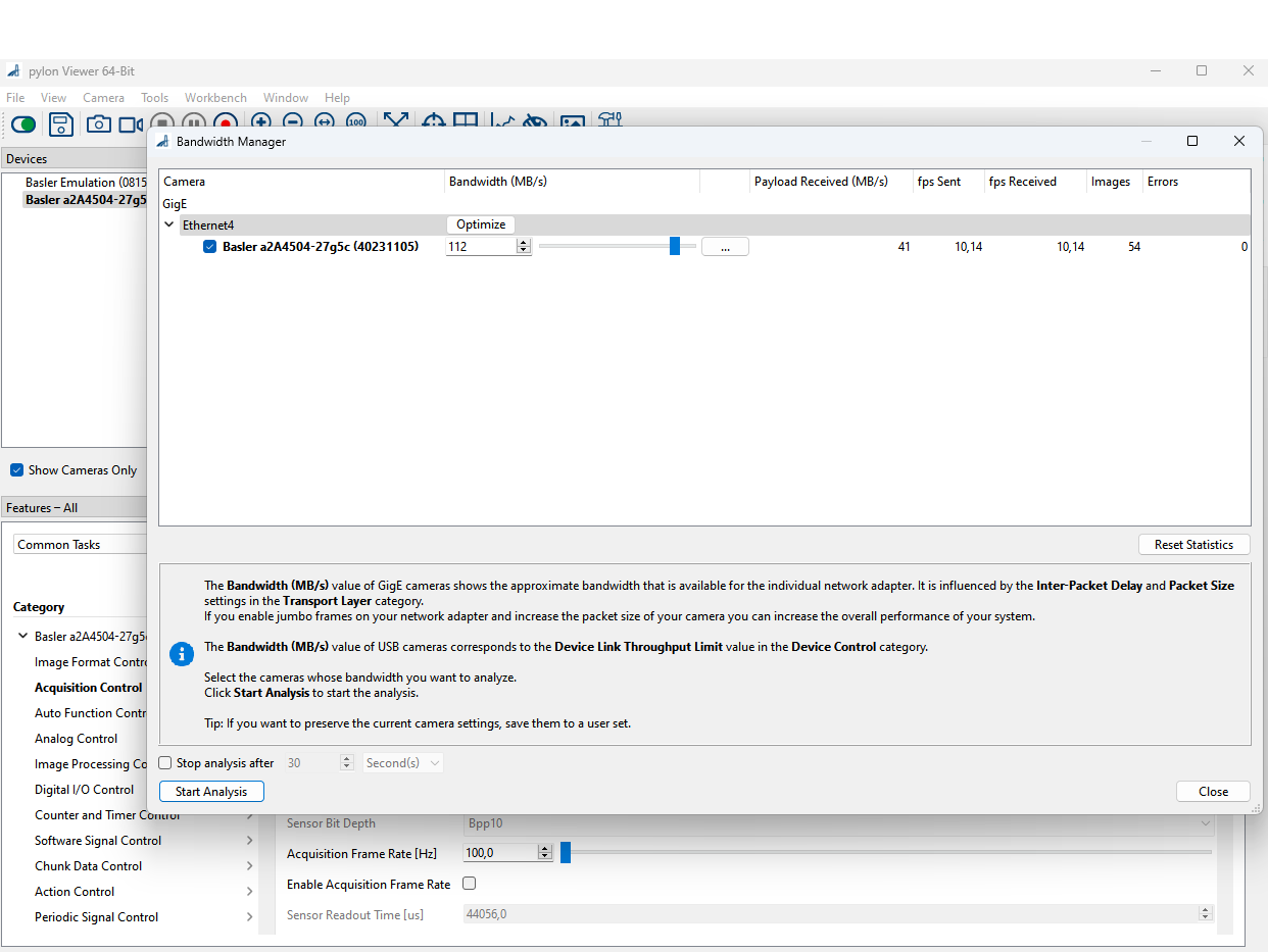
Realizing the full resolution and framerate would require huge bandwidth and a special 5Gbps ethernet interface. We typically run the cameras at more like 100 MB/s, which will impose a frame-rate limit depending on how small the Width and Height parameters of the image are.