Carving 6-axis manipulator
Specifications
Polar range |
-58° … +17° * |
Azimuth range |
-38° … +230° |
Tilt range |
-15° … +25° * |
Base temperature |
18 K |
Maximum temperature |
420 K (150°C) |
* Software limits are in place to avoid collision with analyzer. Negotiable in special circumstances. The hard physical limits are:
Polar -90° … +17° (beam is occluded beyond this)
Tilt -30° … +30° (mechanical motion range)
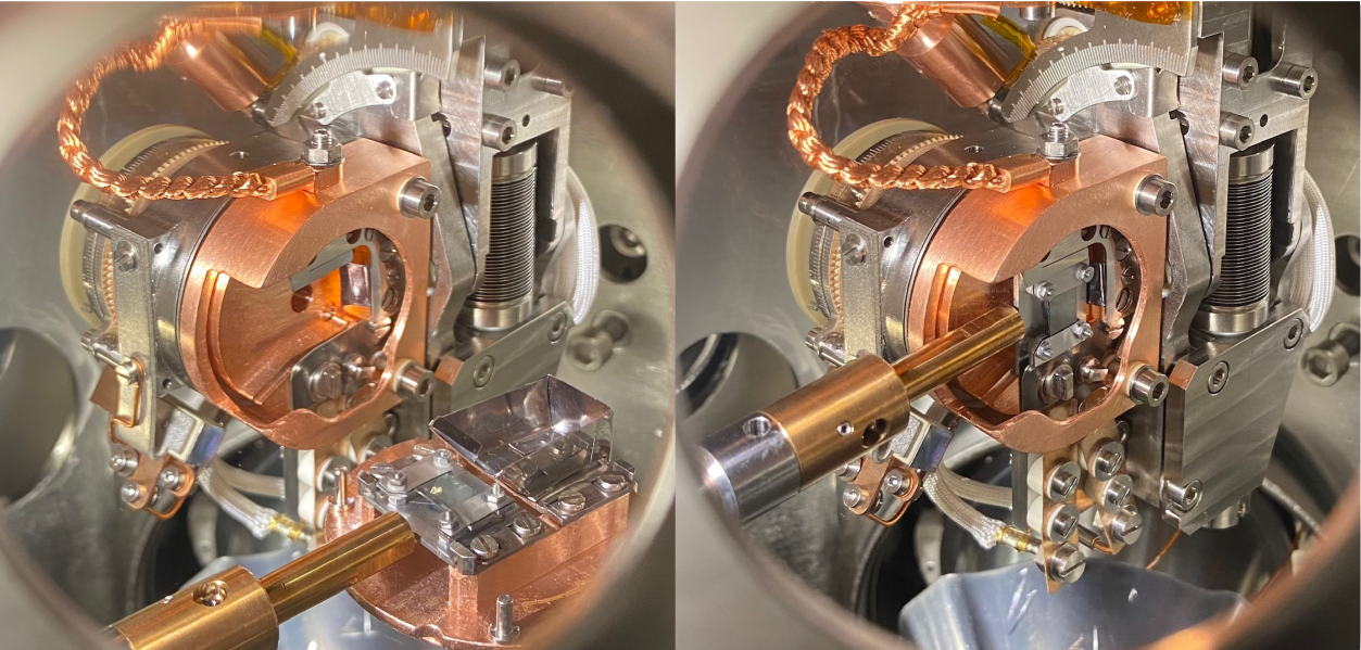
Transferring samples
Samples are collected from the transfer arm and transferred into the Carving receiver with a Specs-style ‘twist to lock’ wobblestick. :
Note
In January 2024 the receiver of the Carving manipulator on the A-endstation was rebuilt. This removes the ability to make two additional electrical contacts at a specific azimuthal angle, but improves robustness, clamping force, tolerance to difference sample plate thicknesses and grounding.
The rebuilt receiver presents a solid ‘C’ shaped piece that sits over the sample plate, with two inverted-slot style in-vacuum tightening screws:
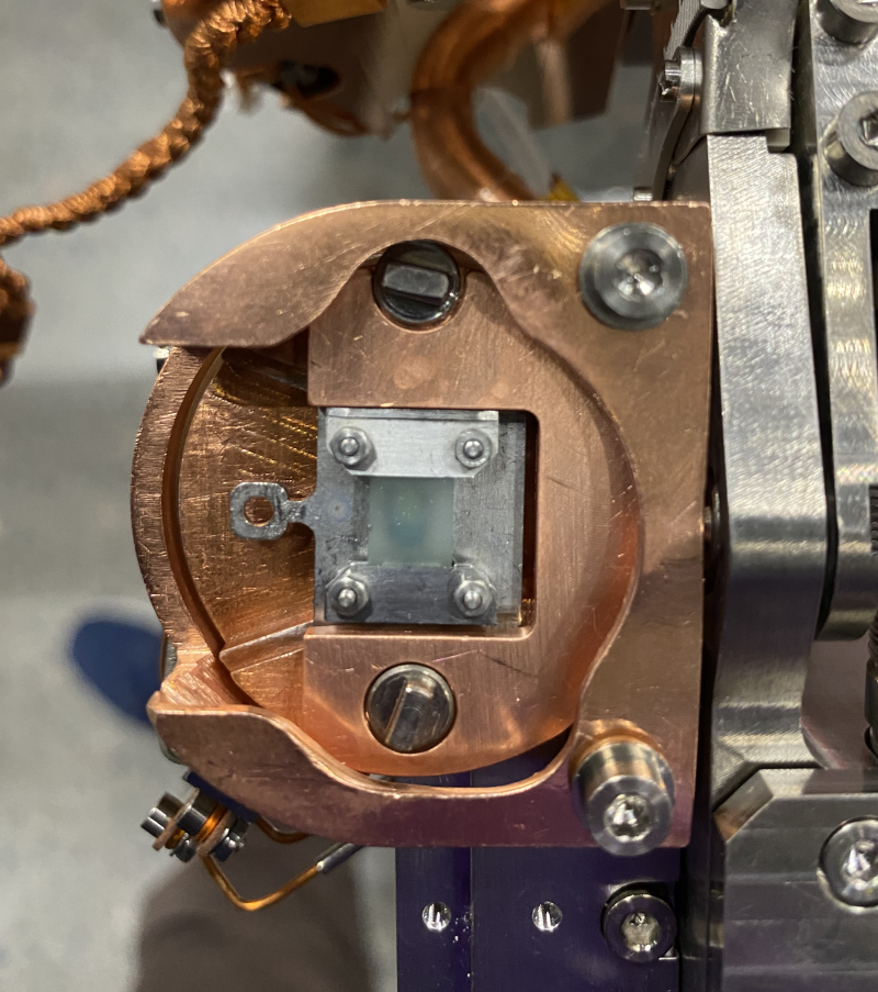
The sample plate sits suspended on small ledges. The highlighted region below indicates where the edge of the sample plate needs to slide into:
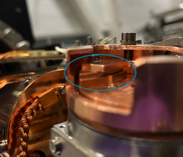
Only a small range of operation is needed for the tightening screws: 1-2 full turns is more than enough from fully tightened to fully loosened. To avoid shearing off the screw head, use only firm ‘fingertip’ force when tightening.
Sample biasing
The sample stage can be electrically isolated from the cryostat and from the cryoshield, making it possible to apply a bias to the entire sample plate. The typical application of this is separating the secondary edges of the sample and of the detector when measuring the sample work function. In principle it is also possible to collect the drain current from the sample and perform an XAS measurement, but this has not been explored and you would be on your own if you want to try it.
The standard configuration of the manipulator grounds everything together. Talk to the beamline staff if you want to apply a bias - a different grounding cable is required. A low-noise supply is available (Keithley 2401 SMU).
Connections and grounding
The sample, inner sample stage and cooling braid are permanently electrically connected. The electrical isolation comes where the main braid connects to the cryostat. Grounding of the sample is achieved solely by a ‘bias’ wire, which runs unshielded inside of vacuum and arrives to one of the pins of the ‘DSH / BIOS’ connector. Typically this pin is grounded by simply stuffing that connector with aluminium foil.
Connectors on the top flange:
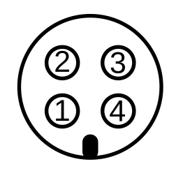
4-pin feedthrough labelled ‘DSH / BIOS’:
Direct current + (unused)
Direct current - (unused)
Bias
Unused
4-pin feedthrough labelled ‘LIMIT’:
End switch for tilt (nose down)
End switch for tilt (nose up)
End switch for azimuth (clockwise)
End switch for azimuth (counterclockwise)
6-pin feedthrough labelled ‘DIODE’:
Unused
Unused
Unused
Unused
Unused
Unused
Heating and cooling
Cooling is accomplished with the Stinger closed cycle He cryostat, heating by a cartridge heater installed in the cryostat.
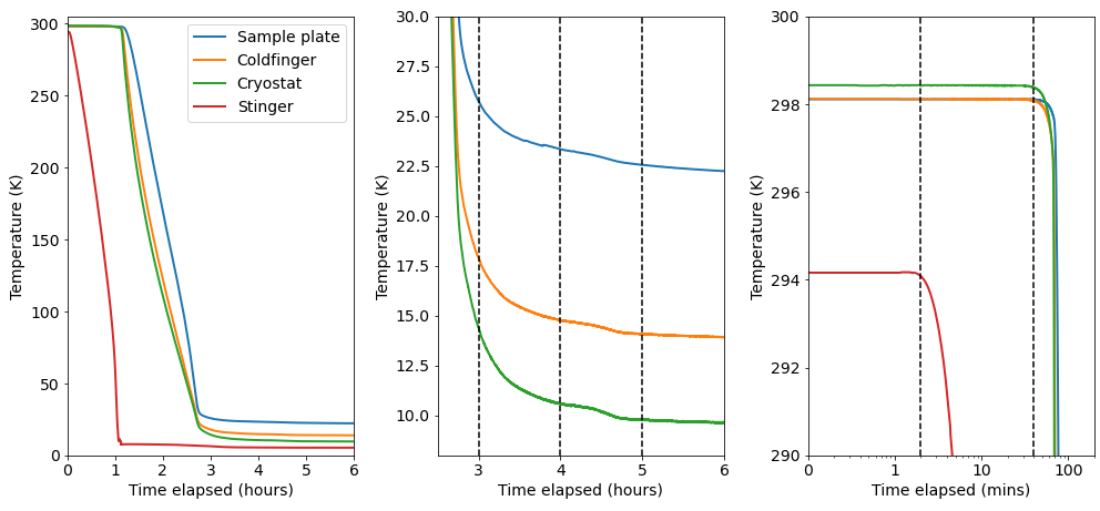
Starting with the entire system at room temperature, a typical cooldown of the Carving manipulator proceeds as follows:
Time elapsed |
|
|---|---|
2 min |
Stinger temperature starts going down |
40 min |
Cryostat and coldfinger temperatures start going down |
3 hours |
Sample temperature within 4K of base |
4 hours |
Sample temperature within 2K of base |
5 hours |
Sample temperature within 1K of base |
Temperature calibration and stabilization
The Carving manipulator has two permanently mounted temperature diodes (DT-670B), one directly on the cyrostat coldhead and another at the end of the ‘coldfinger’ before the cooling braid:
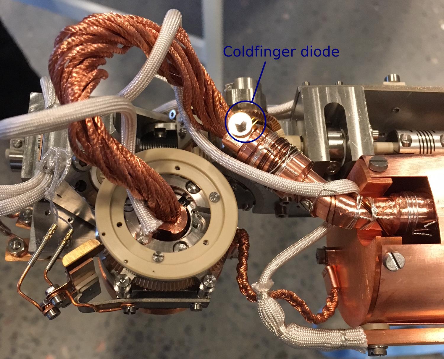
During installation we mounted a diode on a sample plate to see the relationship between the real sample temperature and the two permanently mounted diodes further from the sample stage.
The parameters we care about the most are:
For a given cryostat temperature (which we can always measure), what is the sample plate temperature (which we usually can’t measure)
For a given change in cryostat temperature, how long will it take for the sample plate temperature to settle?
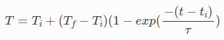
The calibration consists of making a step change in the cryostat temperature and recording the sample temperature response. To a good approximation the sample temperature T evolves as an exponential step function of time t. Based on this we can estimate the final temperature T_f and the time constant tau:
Stabilizing to within n Kelvin of the setpoint will take a time t of:
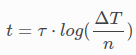
For example, stabilizing to within 1K when stepping from 40K to 50K (𝜏 ≈ 3min) will take 7 minutes while achieving the same when going from 100K to 110K (𝜏 ≈ 13min) will take 30 minutes. 𝜏 is temperature dependent, but as simple worst case scenario one can just assume the highest value of tau that will apply. You do not have to do this calculation by hand, there is a calculator in pesto for this.
Across several different temperature sweeps (different colours), the following was obtained:
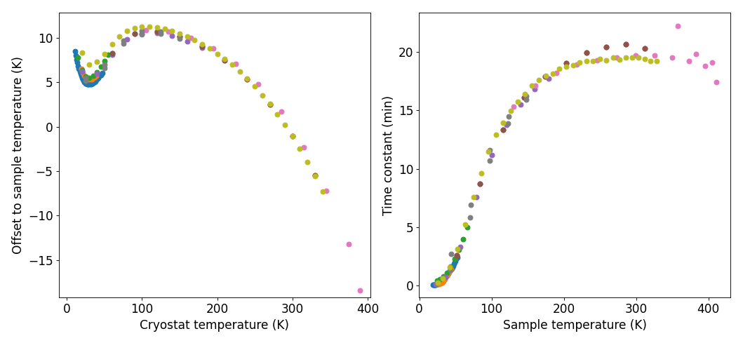
The temperature control scripts use an averaged calibration curve to estimate sample temperature based on the measured cryostat temperature.
Warning
It is important to recognize that such a mapping assumes an instantaneous equilibration. If the interface is showing that the sample temperature is stable, all it actually means is that the cryostat temperature is stable. Do not assume that this means your sample temperature has stabilized. Refer to the time constant discussion above to estimate how long you need to wait before this reported sample temperature matches the true sample temperature.
The temperature measurement and heater control happens through a Lakeshore335 controller, driving the cryostat cartridge heater from the 1.7A output.